Abstract
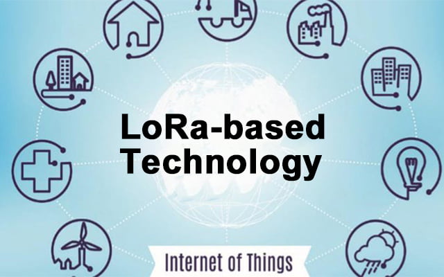
LoRa WAN is a wireless technology for Low Power Wide Area Network (LPWAN). Today, it is considered as one of the most serious alternatives for IoT thanks to its low cost, low power consumption equipment, and its open business model. LoRa WAN specifications propose interesting solutions regarding Medium Access Control (MAC) layer operations to deliver the best communication performances to connected things. Despite its crucial impact on the overall performances, few researchers consider the LoRa WAN MAC layer. This paper presents LoRa WAN MAC layer operations and services based on the LoRa WAN Alliance technical specifications. In addition, it proposes an overview of recent studies related to LoRa WAN performances and stands out the major challenges to be addressed to enhance the performance of data exchanges.
1. Introduction
Since the emergence of the Internet of Things concept, several communication technologies were proposed to provide the services executed by IoT applications. Concurrently, Low Power Wide Area Networks (LPWAN) are proposed as wide-range networks, with reduced power consumption and low data rate specifically designed for IoT. In this context, several LPWAN technologies were proposed for the IoT market. To begin with, Sigfox was the first LPWAN network, launched in 2009. It is a private network based on a proprietary technology acting as a network service provider for IoT applications. Also, Ingenu (formally On-Ramp wireless), is a service provider offering LPWAN via public and private IoT networks based on proprietary technology (The Random Phase Multiple Access). And more recently, LoRa, wireless technology for deploying private or public LPWAN. This technology is using the radio modulation of LoRa based on the chirp spread spectrum (CSS). The MAC operations and the network architecture.
2.LoRa WAN Overview: Network architecture, physical and Mac layers
The network architecture proposed by the LoRa WAN specification consists of several end-devices communicating with one or many gateways in a star-of-stars topology, via single-hop connections. The gateway acts as a bridge that relays, in both directions and in a transparent way, messages between end-devices and a centralized intelligence called the Net Server. The Net Server is connected to the gateway through a wired and/or wireless core network. It is responsible for data exchange and network management. It manages redundant packets, configures parameters related to packet exchanges, and checks security. Outside the LoRa WAN infrastructure, the net server is connected to another application server where IoT applications are deployed. To clarify, the LoRa WAN architecture is presented in Fig1.
The different LoRa WAN entities operate in unlicensed bands, in conformance to the recommendations of local or regional regulatory bodies proposed by ETSI. For instance, the 863-870MHz and EU433 MHz bands are used in Europe, while the US 902-928MHz band is in use in the United States and the CN779-787 MHz in China. Channel access restrictions are associated with these bands on a per device basis. Referring to the LoRa WAN specification, the data transmission in a LoRa WAN system is executed on different channels. Indeed, before starting a new transmission, the end device picks up randomly among its set of allowed channels (limited by the standard to a maximum number of 16). The set of allowed channels can be preconfigured before the end-device association to a LoRa WAN network and updated during the association. Three mandatory default channels must be implemented in each end device for data transmissions on a LoRa WAN network. Three other mandatory channels are used for supporting the communication between the Net server and the end device during the join or association procedure. During, this latter procedure, the Net server is potentially able to update the list of non-mandatory preconfigured data channels with an explicit list of at most five channels.
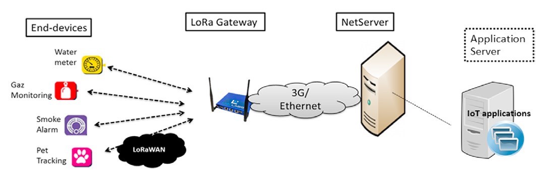 Fig. 1: LoRaWAN architecture
All Mac layer operations executed in a LoRa WAN system; respect specified physical configurations mentioned above. For any operation or data transmission, two types of messages can be exchanged: Unconfirmed messages, which request no response from the Net Server, and confirmed messages for which the end-device requests a response from the Net server. An end-device must first join the network to be considered as an active entity, and that’s how it will be equipped by a set of parameters that are necessary to operate in a LoRa network.1098
3. Data transmission
In the context of LoRa WAN systems, IoT applications can have different needs, regarding the data exchange, energy autonomy, and battery lifetime of the end device. That’s why end-devices are pre-configured according to one of three classes (Class A, Class B, or C) according to their needs. There is no difference in how end-devices proceed to send their messages to the Net Server regardless of the class they belong to. The difference consists in, how and when end-devices receive Downlink messages. In this section, we present these classes in more detail trying to understand how they work, and what differences can we interpret in terms of exchanging data and operating modes.
3.1. Class A
Class A is the basic class implemented in every LoRa end device. It targets applications with low-rate downlink data. It ensures low energy consumption and fits low-powered devices. When a Class A end-device has to send a message to the Net Server (an Uplink message), it randomly chooses a sending channel among the channels configured during the activation procedure. The message is sent using an ALOHA-like channel access technique that takes into account duty cycle restrictions. Once the Uplink transmission is finished, the end-device opens two short receive windows: RX1 and RX2 to listen to a downlink transmission from the Net Server as shown in Fig2. For every
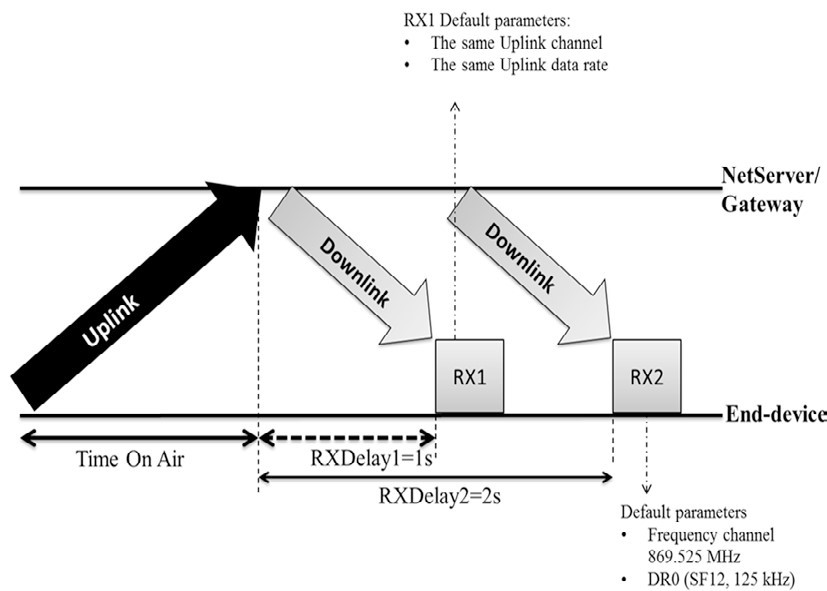
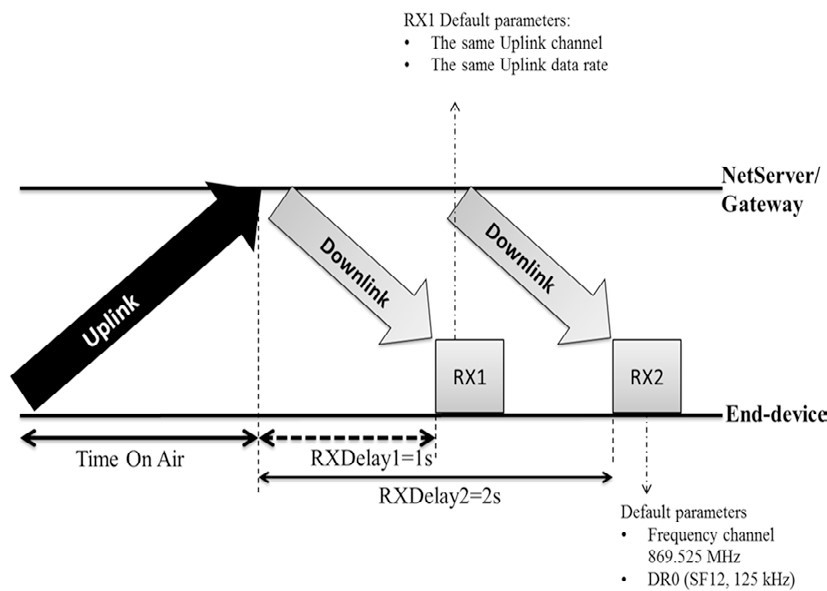 Fig. 2: The exchanging data messages procedure in class A
transmission, the end-device chooses randomly a new channel. RX1 is opened RECEIVE_DELAY1 period after the end of the uplink transmission. listening during RX1 is over the same channel as the uplink one. The data rate used during RX1 is a function of the Uplink data rate and the RX1DROffset field is defined during the Join of the network procedure. The default value of the data rate is the Uplink data rate. RX2 is opened RECEIVE_DELAY2 period after the end of the Uplink transmission on a default channel. For the frequency band EU 863-870MHz, the default values of RECEIVE_DELAY1 and RECEIVE_DELAY2 are 1s and 2s respectively. The default parameters of RX2 are 869.525 MHz for the channel and the data rate DR0 (SF12, 125 kHz) for the data rate. These parameters are configured using MAC commands. If the message, sent by the end-device, is confirmed, the end-device waits for an acknowledgment during RX1. If no acknowledgment is received, it stops listening until RX2. If nothing is received in RX2, the message is retransmitted until an acknowledgment is received or the maximum retransmission number is exceeded (8 retransmissions recommended).
3.2. Class B
Class B is an optional class useful for battery-powered end devices used by applications requiring regular downlink exchanges like actuators. These end-devices have to support higher energy consumption than end-devices implementing only class A. Class B provides more receive windows for downlink communications without changing the uplink communication management. Uplink transmissions are based on ALOHA-like channel access as with class A. An end-device joins the network as a class A entity. For some reasons (e.g. modification of the traffic type or improvement of battery condition) the end-device application layer can decide to switch to class B. In this context, the application layer asks the MAC Layer to search for a beacon message.
The general procedure relies on a periodic broadcast transmission of Beacon messages by the gateway on a fixed downlink channel. The latter is timely divided into periods beginning with the broadcast of a beacon message. Each beacon period is divided into a set of slots that are distributed among end-devices as downlink reception opportunities.
Every end-device opens periodically ping slots to receive downlink messages
The gateway broadcasts Beacon every "Beacon period" time during a time interval "Beacon reserved" defined only for the Beacon transmission. The transmission of the Beacon is preceded by a "Beacon guard" time interval where no ping slot can be placed to avoid collision between downlink and beacon transmission. Once the Beacon message is transmitted, a "Beacon window" is opened where time is divided into ping Slots. The default value of a time ping slot is 30ms. For each Beacon Period, time is divided into 212 ping slots indexed from 0 to 4095. The beacon timing is summarized in Fig3.
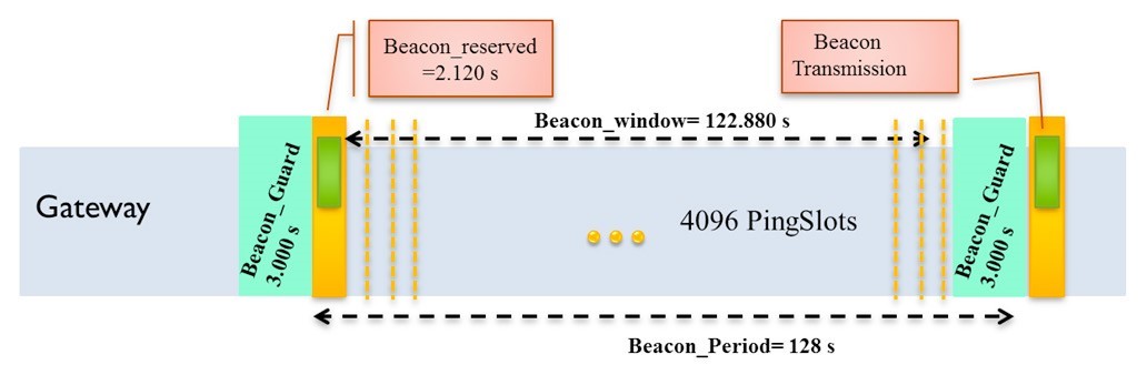 Fig. 3: Class B - Beacon Timing
At each Beacon period, an end-device and the Net Server establish a kind of contract to select the ping slots when the end-device must wake up to wait for a downlink. One end-device and one Net Server calculate a pseudo-random parameter called “Ping Offset”. This parameter is unique for every end-device and it is based on its Dev Addr and Beacon Time. Once the “Ping Offset” is defined, it will be used to calculate all ping slot indexes and their starting times, i.e. when the end-device must wake up to wait for a downlink. Then, the end device can transmit only when it is not listening for a downlink. The server knows that at these times this end-device is listening to the medium. The MAC layer, switching to class B, searches for the beacon message either passively by listening successively to channels or actively by sending a “Beacon Timing Req” which triggers an answer from the Net Server with information on the next beacon timing and the associated channel. If a beacon is found, the application layer selects the ping slot data rate and periodicity and communicates them to the server. In the MAC Payload of the uplink data frame, there is an “F Ctrl” field with a “class B” bit that has to be set to 1 once the end device is switched to class B.
Downlink channel parameters for class B are specific to each band. A default channel is defined and can be modified via a MAC command. For the EU863-870 band, the default downlink channel is the 869.525 MHz channel and the Beacon transmission is based on DR3 (SF9, BW 125 kHz) data rate and a coding rate of 4/5.
3.3. Class C
Class C is also an optional class dedicated to fully powered end devices which consume more energy than other end devices. They require continuous listening to the medium to receive downlink data. Class C implements the same receive windows of class A. However, end devices are listening continuously during the second receive window RX2. After an Uplink transmission, the end device directly opens a short receive window RX2 during the RECEIVE_DELAY1 and before opening the RX1 window. The end device opens then the RX1 receive window. When the RECEIVE_DELAY2 expires, the end device reopens the RX2 until the next uplink transmission. RX1 and RX2 have the same parameters as defined in class A. Fig4 presents how messages are exchanged in class C.
 Fig. 4: The exchanging data messages procedure in class C
4. LoRa in the literature
To evaluate the LoRa technology, several research works have been dedicated to evaluating its performance and identifying the domains where LoRa can be used. In this part, we present researchers which have been interested in the evaluation of the performance, offered by the technology. In the context of the physical layer and the medium access performances, there has been an interest in receiver sensitivity and network coverage. Other features concern the LoRa WAN end-device performance and the scalability of the LoRa WAN network. In the context of scalability and network capacity, other works have studied problems that limit network capacity. The Receiver sensitivity was evaluated by measuring and comparing specified RSSI (Received Signal Strength Indication) to observed RSSI for different Spreading Factors. One of their conclusions was, that the coverage of the network can be improved by selecting a higher Spreading Factor which can be increased by the end device. Also, concerning the network scalability, they made use of both simulation and experiments to show that in the context of the current deployment of LoRa WAN, the scalability of the network is limited by factors like duty cycle, the subdivision of the sub-band, and the number of transmitters. Added to this, different problems limiting the network capacity have been identified. Ferran Adelantado et al. in have studied the network quality in terms of packet transmission for a variable number of end devices. Results show that network capacity is limited by collisions, which increase with the number of end devices. They proved also by a mathematical modelization that the duty-cycle limits the size of the network.
In the same context, an evaluation of LoRa technology scalability has been performed based on simulation, and it was proved, that the channel load has a serious impact on the successful reception of packets. With a link load of 0.48, around 60% of the packets transmitted are dropped due to collisions.
One of the main conclusions outcoming for these researches is the impact of the random channel access mechanism on the overall technology performances. In the next section, we consider with more detail the LoRa WAN channel access management, its current limited performances, and possible issues to offer more efficient MAC layer operations for the technology.
5. Channel access and performance issues
As presented in section 3, the channel access mechanism defined by LoRa WAN is based on an ALOHA-like channel access technique, where end-devices choose randomly an uplink channel for transmission without considering another transmission. This can result in simultaneous use of the channel and a conquest collision between different transmissions.
Evaluations of the channel access mechanism have shown the importance of these collisions with the increase of communicating end-devices. It was proved that the Aloha-based channel access leads to a considerable collision rate which increases the percentage of packet loss in the network. Latter studies have only considered the evaluation of the class A mode. At this stage, the question is whether classes B and C modes may be the required
solution for the collisions problem. Referring to the LoRa WAN specification, these modes provide a more structured downlink exchange management offering for one end-device more opportunity to receive downlink messages.
In, authors have shown that the growth of downlink traffic implies a significant drop in overall collisions and packet loss. This result can give an idea about what can be expected from Class B and C modes. The use of these modes with end-devices and applications requiring significant downlink exchanges is aimed to decrease the reliability of data exchanges and limit the scalability of the network. So, we can conclude that even in a LoRa WAN system implementing class B and C, collisions and packet loss issues will persist.
Today, to allow LoRa WAN technology to conquer areas of use more demanding in terms of quality of service (especially reliability), there is a need to enhance data exchange performances by evolving the channel access mechanism in a way to limit or eliminate the effects of collisions on data exchanges. Several research directions are proposed in the literature.
In, the authors propose to enhance the current random methods with adaptive hopping sequences. This solution can reduce the collision in moderately loaded networks as it will spread simultaneous uplink transmissions over different channels. However, in large-scale networks, there is a great chance that for most transmissions the chosen channel will be already in use, and consequently, collisions would occur. As a second direction, transforming LoRa WAN in a Time Division Multiple Access technologies with centralized scheduling is also proposed to reduce collisions and ensure deterministic performances. Certainly, such a proposal can be a radical solution for the collision problem. However, this will imply a high level of synchronization between end-devices and network, which would be difficult to defend in the LoRa WAN context due to its consequence on end-device power autonomy. From the authors’ point of view, designing a good solution for the enhancement of channel access management for LoRa WAN must be preceded by a clear specification of the context for which the solution will be proposed. This context includes the IoT applications and their performance requirements, the data traffic they are generating, the end-devices hardware constraints, and radio usage constraints (e.g. duty-cycle constraints).
With the coexistence of contradictory needs for heterogeneous applications, proposing a new channel access management resolving the collisions problem is the future challenging research issue for the research community. To sum up, several studies have analyzed and validated the problem of collisions as a critical factor reducing the LoRa WAN performances. In return, no solution had been evaluated to resolve this problem and to enhance data transmission quality. This thematic is an interesting direction for research contributing to a better LoRa WAN quality.
6. Conclusion
In this paper, we have proposed an overview of Lora technology while focusing on a comprehensive description of MAC layer operations as defined by LoRa WAN specifications. In addition, we have proposed a review of recent experimental and theoretical studies related to LoRa. We have combined our knowledge about LoRa WAN MAC layer operations and valuable evaluation results to give a preview of the global data exchange performances of LoRa and future research directions that can be conducted to optimize the use of LoRa.
